Rear Disc Brake Installation Kit For Early Bronco
How to install TOMS OFFROAD's Rear Disc Conversion Kit on a 66-77 Ford Bronco with Factory Ford 9" Rear End.
NOTE: Must remove old bearing retainer plates prior to installation of new parts. When re-using stock axle studs, rotors must be drilled using a 39/64 bit for proper fitment.
Instructions
Jack up rear end and support with jack stands. Remove tires.
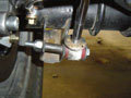
Remove lower bolt in shock mount. Install shock spacer in original bracket. Swing shock to the inside of the lower mount and install new ½”x 4 1/4 bolt with flat washer through the shock as well as the spacer in the original mount. secure with self locking nut. (See illustration 1)
Remove rear drums and the four axle retaining nuts. Remove axle shaft, brake backing plate and emergency brake cables.
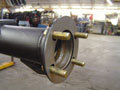
Install 1/8″ spacer plates with 4 new retainer bolts provided.
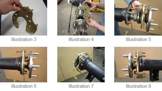
(See Illustration 2)Place the upper caliper bracket bolts in base caliper bracket, threaded end toward inside. (See Illustration 3)
Slide the axle shaft back into the housing, just until the bearing starts into the housing bore.
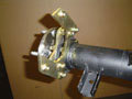
Drop the base bracket into place (U-shaped cutout facing down) with the 4 bolts hanging in the bracket facing towards the center of the housing. (See illustrations 4 & 5)
Shove the axle shaft all the way into the housing and place the lock washers and nuts on the 4 retaining bolts holding the axle in. (See Illustrations 6 & 7)
Bolt Torque:
50 ft/lbs for ½” axle retaining bolts
30 ft/lbs for 3/8″ axle retaining boltsInstall 2 thick and 1 thin, two-holed spacers on the upper & lower bolts on the caliper base plate (See Illustration 8 above). These spacers may need adjusting in step #13.
Install the upper mounting plate onto the base plate making sure the welded nut plates are facing in toward the center of the differential. Fasten the bracket using 4-3/8″ lock washers and nuts. Torque nuts to 30 ft/lbs. (See Illustration 9)
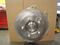
Install rotors. (Make sure mating surfaces are clean from rust and dirt). Install a couple of lug nuts to hold rotor in place. (See Illustration 10)
Rotate rotors and check for wobble or obstruction. If there is any wobble, check for interference in the mating areas. If not, then the axle and rotor bolted together should be faced to true up. Mark the position of the rotor and axle so that it can be installed the same way if the rotors are removed in the future.
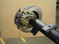
Install the calipers so that the bleed screw is at the top facing forward. If it is on the bottom use the other caliper. Make sure the projections on the caliper don’t interfere with the bracket. Remove spacers as needed between base mount and caliper support bracket (See Illustrations 8 & 9 above) until caliper drops over rotor and fits properly against caliper mounting plate. (See Illustration 11)
Install new steel brake lines from the stock center brake hose out towards calipers.
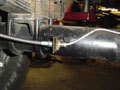
Install braided stainless hose to caliper with a copper washer between the caliper and hose and between the hose and banjo bolt and loosely connect to new steel housing lines. This will determine mounting locations for brake line support tab. They are made to be mounted on the rear of the axle tubes, approximately 2″ in from the center of the inner u-bolt. Applications may vary slightly.
Weld brake line support tab to housing or attach tab to housing with a clamp. Route brake hose around back side of shock. (See Illustration 12)
Tighten all brake hose connections.
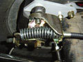
Install cable through caliper spring to caliper e-brake lever. Snap the brake cable housing into the cable support.
Route cables up to center cable attaching point. Cables are made to go above the leaf springs. Secure as needed to protect from exhaust, drive line.
Mount cables in body support bracket with supplied clips. Attach to factory e-brake linkage and adjust. The GM rear caliper with integral parking brake is self adjusting when you use the parking brake. As the pads wear, it will click to the next stop. But, they do not always work and they will not work if you do not use your parking brake. To adjust the parking brake the fast way, remove the arm from the caliper, turn the shaft as far as possible and reinstall the arm. (See Illustration 13)
Bleed air from system. Gravity bleed first: fill master cylinder level, open rear bleed screws until clean fluid comes out. Keep master cylinder full. Close bleed screws.
Bleed entire system. Use RR, LR, RF, LF sequence. Bleed until you have clean, clear fluid with no air bubbles. Install wheels and torque.
Test braking system in an empty parking lot or driveway. Make several stops of varying levels – light braking, medium braking, hard braking (panic stop). Note operation of brakes: pedal feel, wheel lock up and stopping power.
Troubleshooting
1. Gravity bleeding. Calipers, especially rear calipers with all the parts and crevices, can trap air inside them. Gravity bleeding is the best method we have found to bleed calipers. To gravity bleed, remove the caliper from the bracket and leave the rubber hose attached. Take the top off the master cylinder and keep filled. Hold the caliper so the flex hose is going slightly uphill to the caliper. Open the bleed screw so fluid and air will slowly come out of the bleeder. You can move the caliper around, tap it lightly with a rubber hammer to help knock the air bubbles loose. When the fluid runs clean and clear, close the bleeder . Do the other side. Do both calipers again. (Do not push the pedal until you reinstall the calipers on the rotors.)
REMEMBER that air bubbles rise. The bleed screw must be at the top where it breaks into the caliper cylinder to get the air out. The bleeder will be pointing toward the front.
2. Adjust Caliper Parking Brakes. The GM rear caliper with integral parking brake is self adjusting when you use the parking brake. As the pads wear, it will click to the next stop. But they do not always work and they will not work if you do not use your parking brake. To adjust the parking brake the fast way, remove the arm, turn the shaft as far as possible and reinstall the arm.
3. Remove residual valve (s). The residual valve holds 10 pounds of pressure on a drum brake system when the brakes release to keep the springs on the shoes from collapsing the wheel cylinders. Residual valves can be found in the end of the cylinder on single master cylinder (66 only) where the brake screws in. On a dual master cylinder system, they can be found in both ports with drum brakes. One in the rear line only on front disc, rear drum systems, or in the combination valve rear line only. You can remove the residual valve from the master cylinder where the brake line screws in the a sheet metal screw. Screw it in and pull. It should come right out.
- 2 – Rotors
- 2 – Caliper Bracket Kits
- 2 – Loaded Calipers w/Emergency Levers
- 2 – Banjo Bolts
- 2 – Braided Stainless Steel Caliper Hoses, Brackets & Clips
- 2 – Steel Brake Lines
- 2 – Emergency Brake Cables
- 2 – Shock Mounting Bolts and Spacer Sleeves
More Ways To Get Help & Learn More